10 June 2021

GPS and Raspberry Pi Stratum 1 Server


This is certainly not a difficult project, but I am going to assume you can put a hat on a raspberry pi, get the OS installed and do some basic command line work. (hint: Don't forget that blank file named ssh in the root of the boot drive so you can remote in)

Scope

Time is essential to any communication method, but particularly so to low-power digital communications in ham radio.  Modes like FT8 or JS8 utilize a single RF frequency and utilize the Audio bandwidth to handle multiple stations.  To accomplish this, everyone has to be transmitting and decoding in fairly exacting time segments.  In my attempt to be more effective in a grid-down scenario I started building local NTP servers that would provide a time standard, separate from the internet, for my radio shack, etc.  I started with a simple USB GPS receiver on a Raspberry PI over wifi, and now this project is to build a hardwired server with a serial GPS receiver that has PPS (pulse per second) timing.


Version 1

Resources

Julian: OH8STN Video on the original GPS PI
Mike Richards: The Original, as far as I am concerned, walkthrough of the GPS PI
Rob Robinette: Troubleshooting resource for this setup
UPUTRONICS Setup

Parts List

Raspberry Pi 4
Micro SD Card
Uputronics GPS/RTC Expansion Board
Uputronics Active GPS Antenna
ThePiHut Pi GPS HAT Case for Raspberry Pi 4
(Optional) 12 volt to USB charger
(Optional) PoE splitter
Some form of power supply for Raspberry Pi 

Process

To be clear Version 1 of this project, as detailed by Mike and Julian in the resources is MORE than adequate for most people.  Below is an estimated error comparison between just using the NMEA stream and then using the PPS versus standard internet NTP sources.


As a reminder, a second is bigger than a millisecond (ms) which is bigger than a microsecond (µs) which is bigger than a nanosecond (ns).

I have no hesitancy recommending the Version 1 GPS Pi and you can follow the first two resources and it will be excellent.

If you want to play with the PPS part, read on.

The HAT I used is a little different in the way it works.  The baud rate for the GPS unit is faster than standard, and it uses the kernel PPS instead of SHM 1 on the serial unit.  That being said, it is easy to set up and I think it is the best one available.

I am using Raspberry Pi OS released 2021-05-07

Once you get the raspberry pi up and running and are logged in:
sudo raspi-config
Select Interfacing Options and Enable I2C

Next, we will install the tools to read the Real-Time Clock and the PPS signal from the expansion card
sudo apt -y install python-smbus i2c-tools pps-tools
And make sure you see 42 and 52 show up in the command below
sudo i2cdetect -y 1
Next add real time clock, pps, and activate the onboard serial port by adding these three lines to config.txt
sudo nano /boot/config.txt
dtoverlay=i2c-rtc,rv3028
dtoverlay=pps-gpio
enable_uart=1
(ctrl-x and y to exit nano on all of these.  You can try VI but on pi it doesn't always work right on my terminals)

Next, we want to make sure the onboard console is not interfering with our gps serial connection
sudo nano /boot/cmdline.txt
Delete this part of the first line: console=serial0,115200 (if present)

Next, execute the following commands to get rid of the fake hardware clock on the pi
sudo apt-get -y remove fake-hwclock
sudo update-rc.d -f fake-hwclock remove
sudo systemctl disable fake-hwclock
sudo nano /lib/udev/hwclock-set
and comment out the following 4 lines
#if [ -e /run/systemd/system ] ; then
# exit 0
#fi
# /sbin/hwclock --rtc=$dev --systz --badyear
To set the baud rate we mentioned before add the following line to rc.local   BEFORE the exit command
sudo nano /etc/rc.local
stty -F /dev/ttyS0 115200
Add PPS to modules
sudo nano /etc/modules
pps-gpio
and reboot
sudo reboot
After reboot, you can test the PPS part with the following command:
sudo ppstest /dev/pps0

You can optionally use minicom to test the GPS over serial or you can do a cat command.  Either way, you can see what serial ports are being used for either.  In my case it was /dev/ttyS0
ls -lh  /dev/serial[0,1]
Option 1
sudo apt-get install minicom
minicom -b 115200 -o -D /dev/ttyS0
Option 2
sudo cat /dev/ttyS0
Once you are comfortable that things are working, we can install chrony and gpsd.  Goes between the GPS device and Chrony.  Chrony is our NTP server.
sudo apt -y install gpsd gpsd-clients python-gps chrony python-gi-cairo
We will configure GPSD to read NMEA and PPS signals.
sudo nano /etc/default/gpsd
 START_DAEMON="true"
 USBAUTO="false"
 DEVICES="/dev/ttyS0 /dev/pps0"
 GPSD_OPTIONS="-n"
Next at the bottom of the Chrony config file, modify the makestep and add the lines to add NMEA and PPS.  The last line could be allow all, but this lets you limit to only respond to NTP requests from your network.
sudo nano /etc/chrony/chrony.conf
makestep .1 5
refclock PPS /dev/pps0 refid PPS prefer
refclock SHM 0 refid NMEA

allow 10.0.18.0/24
and reboot
sudo reboot
At this point, you should be able to point your clients to the IP address of your NTP server and you are off to the races!

Tools


The following 4 commands will tell you a lot about your system and what to troubleshoot.
gpsmon -n

This will tell you what is coming off of your GPS receiver
chronyc sources -v
This will tell you what is being used by chrony and how it relates to the other available time references.
sudo timedatectl


This will show you all the time standards used by the hardware pi.
sudo chronyc makestep
This will force your hardware to sync up to the time reference immediately, otherwise, it does it in steps.
After you are sure it is working, mount it somewhere handy.  I have it in the shack right now, but I do have a power over ethernet (PoE) injector and splitter so I can put it anywhere in the house and keep the cables down.  I also recommend setting up RaspAP on it so that it can host its own hotspot if your network goes down and you still want to use it as your time reference.


29 May 2021

2021 Ham Shack Update

I have spent the last several months getting my 11th base QTH (home base station) set up so that it is usable by my kids as part of their science curriculum next year.  I must say that of all my setups, both fixed and mobile, this is my favorite.  I thought I would take a moment to walk through what I have running in my shack.  A lot of these things deserve their own post, but I needed to start somewhere.  I included links for reference.  Much of my equipment is no longer available, or no longer available for the price I got it at, etc. None of these are affiliate links or anything like that (Not that I would be opposed to them, wink wink, nudge, nudge).  I can say I have had great luck with Ham Radio Outlet, Gigaparts, Antenna Farm, and KF7P Metal Works.

I have been a licensed Amateur Radio (Ham Radio) operator since 1998, and my goals have stayed about the same.  I got into ham radio for:

  1. Playing with science
  2. Participating in Emergency preparedness and disaster recovery
  3. Engaging with like-minded people

It's funny that when I take breaks from ham radio it is usually the people that bring me back to it, when I replace equipment it is dictated by what could be used in an emergency... but what keeps me up at night scheming and planning is still the idea of modulating radio waves with some form of information... and being able to do something with it... often over a fair bit of distance.

Having been in this for 20+ years, I have had several different setups.  They probably each need a review at some point of what I did right and what I did wrong.  I like to think I evaluate those things as I design the next one... but sometimes I think I just put things where I think they will look cool, and be accessible to my operating style.

Circa 2008 with my oldest child, operating an antique Vibroplex bug.

Man, what did I do with those LED lights...that was sweet

This is the same setup as the picture above, circa 2016.  I was a VP of Engineering for a startup.  In many ways, it was the most fun work I have done, designing and prototyping hardware.  This was also the first countertop desk I made.

Preparing for our move across the country in 2017.

One of several folding table stations I have had over the years.

My first attempt at a station in this house.  It never really worked out, couldn't get cables ran out of the room in a functional way.

Final throw-back to the worst antenna setup I ever did.  I was stupid and put it way too close to where the power came into the house.  We are lucky there was no incident... but don't be me... don't be dumb

So, onto the present shack:  
The desk itself is an L-shaped countertop with shelving along part of the backstretch for radios.  The Bottom shelf does extend over the desk for easier operation of the rigs.  My primary desktop sits next to the station rack, and 120v UPS sits below.   

The eventual goal is to get all the wires and such off the floor. I have 3 kids under 2 years old right now, and my kids have always been welcome in my radio shack.


The coax generally exists in varying states of disarray, but in this case, it is run and tidy.  You can also see a ground bus behind the second shelf, which is all tied to the main ground, and ground rods outside.  I use DRF-400 low-loss coax for 90% of my runs.

From my primary operating position, I use an Icom IC-7300 for HF and an Icom IC-9700 for local VHF/UHF work and satellite operation.  I go between a Shure SM-58 and a Sennheiser MD-421 II as my microphone on HF, and generally use the standard hand-mic on VHF/UHF.  Headphones are the Beyerdynamic 250 OHM DT 770 Pros with a JDS Labs Headphone preamp.  My CW key is a Begali Simplex.

I am a systems administrator by trade so every chance I get to rack things... I do.  On top of the rack is a mess of DC power distribution.  The next unit down, with the front plug, is a Furman power conditioner.  Then a power distribution unit.  Anything in a radio path is either on DC or goes through the power conditioner.  Then there is an 8 port Cisco 2960G that connects to my main rack via fiber so that everything is isolated.  Next is cable management and a West Mountain Super PWRGate.  Below that is an Astron SRM-50M.  The fans below that are switched controlled, but hardly ever needed.  The space below that is about 30ah of battery backup.

The aforementioned mess of 12-volt wires.  Everything is fused and terminated in power-poles.  I use a West Mountain RR/4008H for distribution.  On the left, you can see the USB power supply for my tablet and surface and a USB switch to switch the two main radios between my Surface Pro 7 and my desktop.

While it certainly deserves its own post, I am now running an APRS digipeater/IGate using an old Yaesu FT-2800M and a Microsat WX3IN1 Plus 2.0.  At some point it will get weather added to it... but I am not there yet.

Moving out of the shack and into the adjoining utility closet is a used Motorola SLR-5700 that I am in the process of repurposing as a DMR repeater.


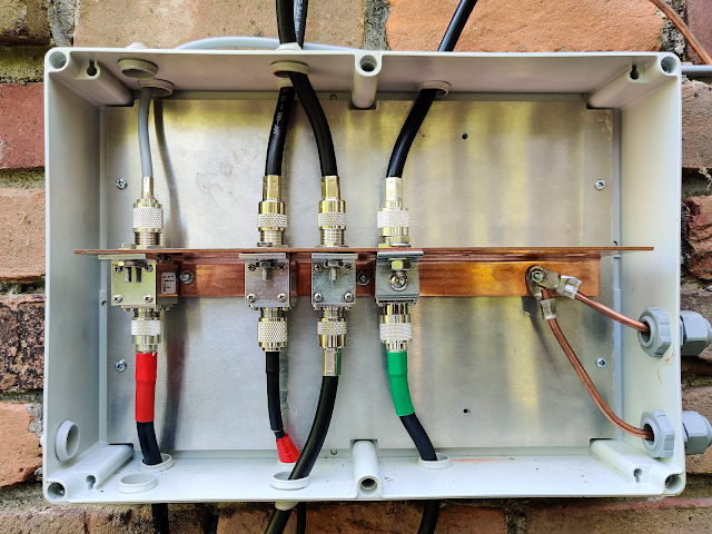
Moving a little further out, you can see the generator and lightning protection. I use Polyphasers for most things, but also have an Alpha Delta for passing DC to the 440 preamp on the roof.


Finally, some pictures of the M2 Eggbeaters I use for both terrestrial and satellite VHF/UHF work.  Still working to clean up the install, but they work and I have made lots of contacts on them.  I do use a SSB-Electronic SB-70 Preamp on 440MHz.  Currently, I am using a very sloppy G5RV for HF, but it is not really worth taking a picture of.

Also pictured throughout, but not as exciting to talk about: